
The PXB and Signal Generator nodes settings include closed loop settings that are the same with the exception of the Signal Generator node property checkbox of HARQ/TA Test Support. To use closed loop feedback with a signal generator, this box must be checked.
These settings setup the instrument to receive feedback signaling from the eNB/base station. For LTE Clause 8 tests, additional settings are provided to configure how the PXB or Signal Generator responds to the received feedback signal.
There are four settings within the Closed Loop Feedback Configuration section of the instrument node settings window:
Mode—select the feedback signal type using the drop-down menu
Dedicated(Serial Data)
Multiplexed(Level Triggered)
AUX Port Pin
Use the drop-down menu to select which pin on the AUX IO connector receives the feedback signal.
Baud Rate
Applicable when using the dedicated mode (Dedicated)Serial Data))
Data Polarity
Use the drop-down menu to make the selection.
The feedback signal must be sent for every subframe.
The dedicated signal type uses a serial format with an LV TTL RS-232 type protocol. Baud rate selections up to 460800 are supported in this format. Refer to the Baud Rate property drop-down menu for the baud rate selections.
Each signaling transmission consists of an 8-bit character: b7 b6 b5 b4 b3 b2 b1 b0. The least significant bit (LSB) is b0. The signaling transmission consists of a start bit set to '0', followed by 8 data bits transmitted LSB first. The last bit of the transmission is a stop bit that is set to '1'. The following figures illustrate this serial bit pattern for both positive and negative polarities. The middle figure includes the hex value.

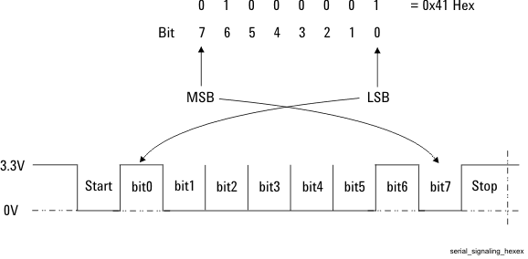

These serial command signals connect to one of the instrument's AUX I/O connector pins AUX0 to AUX11. The selection for a pin is done using the AUX Port Pin property drop-down menu. The serial format transmits 8-bits at a time to the instrument. These bits can be mapped to the auxiliary signaling functions using the Closed Loop Test Settings node.
This HARQ feedback signal uses bit 4 for the ACK, or NACK: This is the only bit used by the software.
ACK bit value is '1'
NACK bit value is '0'
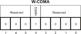
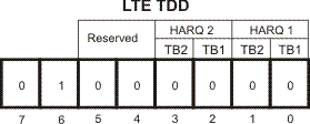
To determine whether a signal is for HARQ or timing adjustment (TA), the serial data dedicates bit 7 and bit 6 for the signal type:
"00" means that bit 5 to bit 0 are recognized as a TA command
"01" means that bit1 to bit 0 are recognized as an HARQ ACK/NACK command
The following figures show the variations for bit 7 and bit 6.
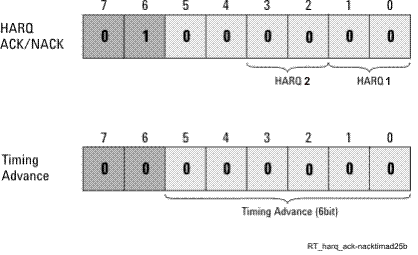
The timing advance (TA) command has 6-bits, the value range is 0 to 63, which is defined as TA, in the 3GPP standard TS 36.213, 4.2.3 Transmission timing adjustments section.
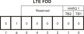
The HARQ command uses two bits of serial data, bits 1 and 0 (HARQ 1 in the figures). A NACK is '0' and an ACK is '1'.
Bit 1 contains the HARQ feedback for transport block (TB) 2 during UL MIMO operation, otherwise this bit value is '0'.
LTE FDD and TDD Clause 8 test, 8.2.1A is an example when Bit 1 is used.
Bit 0 always contains the HARQ feedback for transport block (TB) 1 during all feedback transmissions.
LTE TDD also uses a second HARQ command (shown as HARQ 2 in the figures) when the UL/DL Configuration is set to 0 (number of DL subframes > number of UL subframes). This second HARQ command uses bits 3 and 2 of the serial data, and their data is the same as bits 1 and 0 respectively. The conformance tests use only UL/DL Configuration 1, so the HARQ 2 command is not used. The software does allow changing the UL/DL Configuration value, but then it would be outside of the conformance test settings. Always refer to the standards before making test setting changes.
The following figures show the HARQ commands for both LTE FDD and LTE TDD.
The eNB/base station sends a binary signal that conforms to the instrument's multiplexed mode requirements. The multiplexed mode accommodates commands that are 1- to 12-bits wide and sent as a low-voltage, 3.3V TTL format signal where 0-volts represents a ‘0’ and 3.3-volts represents a ‘1’. This signal is input to one of the AUX I/O connector pins selected in the AUX Port Pin property drop-down menu.
The feedback signal is sent once every frame.